

Installing GNS3 can seem complex, but this guide is here to make it easy. We’ll take you through every step, ensuring you understand how to get GNS3 running, no matter your skill level.
By the end of this guide, you’ll not only have GNS3 installed but also know how to set up your first network lab. You’ll learn by doing, which is the best way to get a solid grasp of network simulation with GNS3. Let’s get started and explore all that GNS3 has to offer for your networking projects.
Install GNS3 for beginners
Before You Begin, Here’s What You Need
GNS3, or Graphical Network Simulator-3, is an open-source software that lets you design, simulate, and test virtual networks with complex topologies. You can use GNS3 to learn and practice networking skills, prepare for certifications, test new configurations, and troubleshoot issues. GNS3 works with IOS images from Cisco and other network devices from various vendors.
GNS3 System Requirements
Before you embark on installing GNS3, it’s crucial to ensure that your system meets the necessary requirements. This will not only facilitate a smoother installation process but also guarantee that GNS3 runs efficiently on your machine.
Minimum System Requirements for GNS3
Based on the official GNS3 documentation, the minimum system requirements for installing GNS3 are as follows:
| Item | Requirement |
|---|---|
| Operating System | Windows 7 (64-bit) and above, macOS 10.12 (Sierra) and above, or a modern Linux distribution |
| Processor | A minimum of an Intel Core i3 or equivalent |
| Memory | At least 4GB of RAM, though 8GB is recommended for optimal performance |
| Storage | 1GB of free disk space for GNS3 installation. Additional space will be required for operating |
| Networking | Ethernet or wireless network interface card recognized by the host operating system |
For more detailed and specific requirements, please refer to the GNS3 documentation.
Recommended System Requirements for GNS3
Drawing from our experience at Dynamips, we recommend the following system specifications for installing GNS3 on Windows to ensure an excellent experience when running and testing various scenarios:
| Item | Requirement |
|---|---|
| Operating System | Windows 10 (64-bit) or macOS 10.14 (Mojave) and above |
| Processor | Intel Core i5/i7 series or better |
| Memory | 16GB of RAM or more |
| Storage | SSD with at least 35GB of free space |
| Networking | Gigabit Ethernet NIC for improved network simulation |
These recommendations aim to provide a smooth and responsive GNS3 experience, allowing you to focus on learning and experimenting without hardware limitations.
Additional Considerations
Virtualization Support: Ensure that your CPU supports virtualization (Intel VT-x/AMD-V) and that it’s enabled in the BIOS settings.
Graphics: A graphics card that supports hardware acceleration can enhance the user interface responsiveness.
By adhering to these requirements, you’re setting yourself up for a successful GNS3 installation. Remember, the more powerful your setup, the more complex network simulations you can run. Now that you’re aware of what’s needed, let’s proceed to the installation steps and get you started with GNS3.
Step 1. Essential Steps Before You Install GNS3
There are several methods to install GNS3, each with its own set of steps and requirements. However, based on our extensive experience at Dynamips, we highly recommend using VMware Workstation for the installation process. This method provides a stable and efficient environment for running GNS3 and allows for the creation of complex network simulations.
If you already have VMware Workstation installed on your system, you can skip the initial setup and proceed directly to the second step. If not, let’s start by installing VMware Workstation, which is a powerful virtualization software that enables you to run multiple operating systems on a single physical computer. For those who prefer a cost-free option, VMware Player is an excellent alternative that doesn’t require a license. By using VMware Player or Workstation, you can simplify the GNS3 installation process, making it more accessible and straightforward.
In the following sections, we’ll guide you through the installation of VMware Workstation. Once that’s complete, we’ll move on to installing GNS3, ensuring you have an optimal setup to begin creating and testing various network scenarios.
How to Install GNS3 with VM on windows 10?
To install GNS3 using a virtual machine (VM), you can follow these general steps:
If you haven’t already, download and install VMware Workstation Player for Windows or VMware Fusion for Mac. VMware is recommended because it’s faster and supports nested virtualization
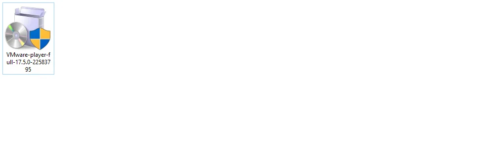
1-1. To download VMware Player, go to this link and download the setup file.
Tips: After you download the setup file, you should see the downloaded file like the screenshot below.
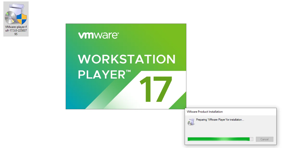
1-2. Next, you need to double-click on the VMware Player setup file to start the installation on your PC.
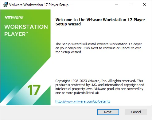
1-3. When the installation wizard appears, click → Next to continue.
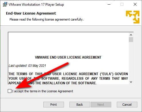
1-4. You need to accept the license agreement to proceed.
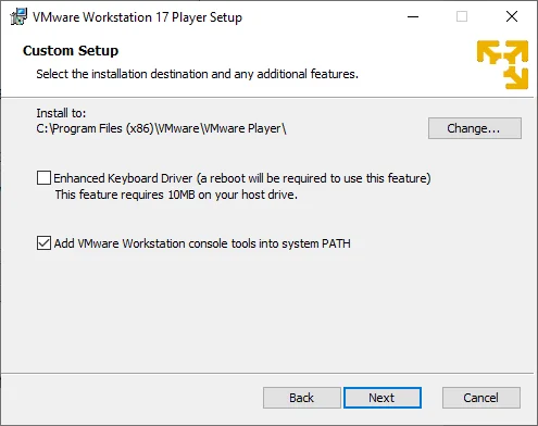
1-5. In this step, you can choose whether to enable the Enhanced Keyboard Driver option or not. This option improves the keyboard compatibility for some non-English keyboards. Click → Next to continue.
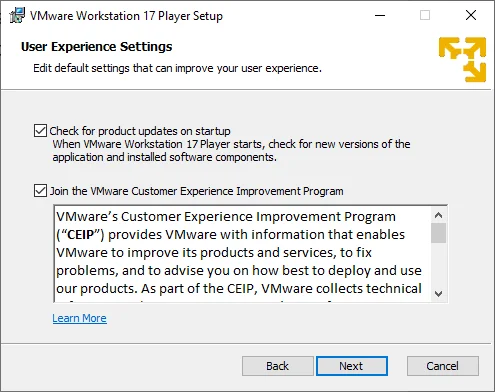
1-6. Then, you need to choose whether to check for product updates or join the VMware Customer Experience Improvement Program. We will leave these options as default and click → Next to continue.
1-7. You can also choose whether to create a shortcut on your desktop or start menu for easy access to VMware Player.

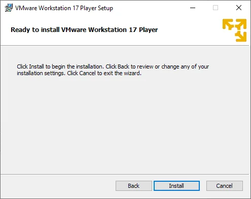
1-8. Now, you are ready to install VMware Workstation on your Windows PC.
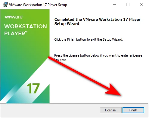
1-9. Congratulations, you have successfully installed VMware Workstation Player. To install GNS3 on your system, click → Finish.
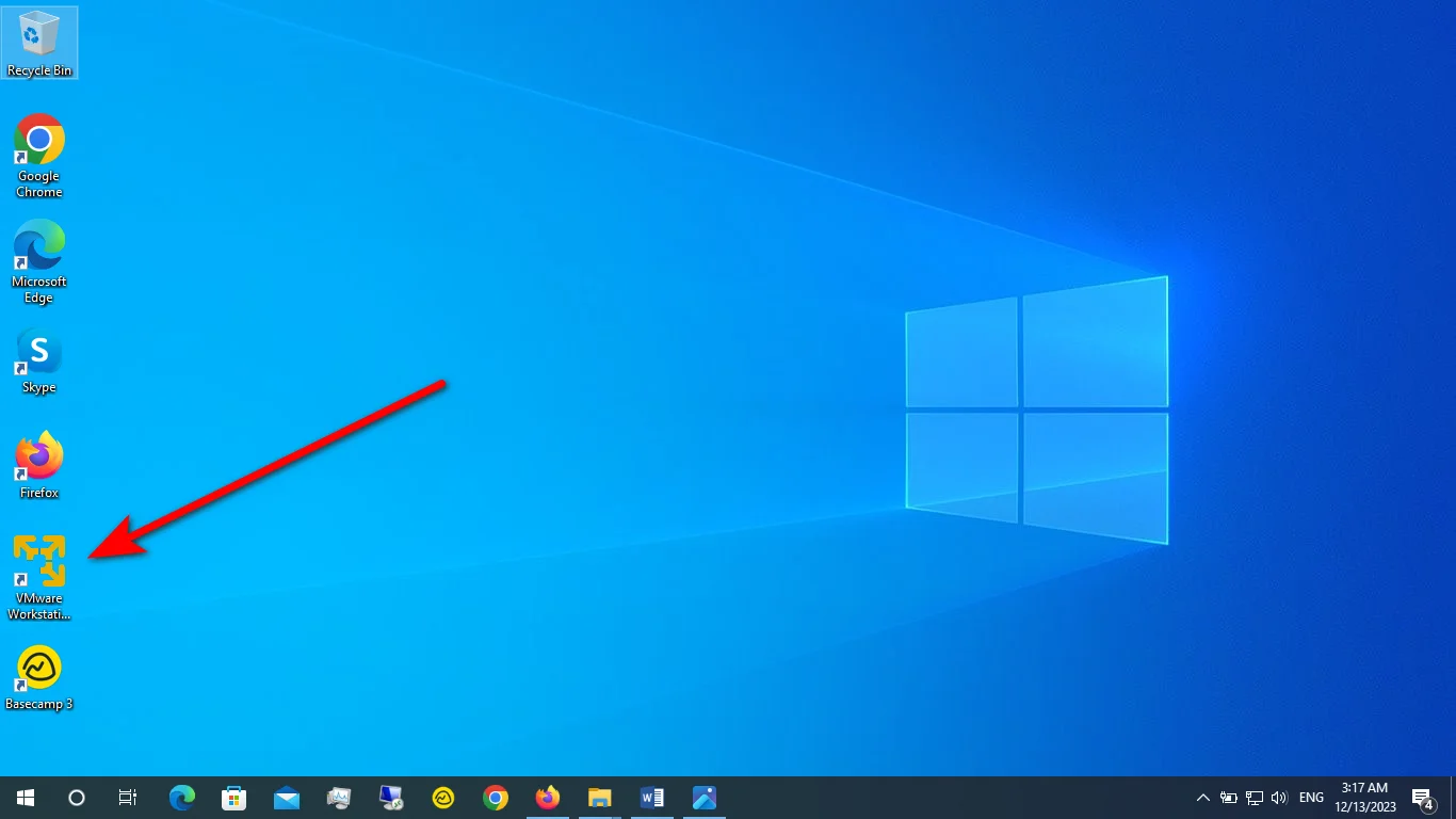
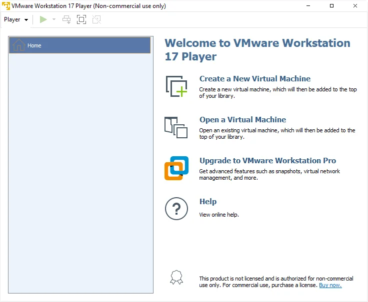
1-10. On your desktop, you can see the VMware Player icon. You should double-click on it to launch it.
Completing Your VMware Player with GNS3 Setup
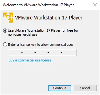
1-11. You have two options. You can use the free non-commercial version by clicking on the option below and then clicking → Continue.
1-12. Finally, click → Finish.
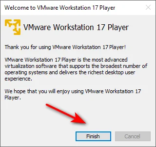
Now, VMware Workstation Player is ready for you to use.
Step 2. Download & Import the GNS3 VM
To use GNS3, you need to download and install two components: the GNS3 installer and the GNS3 VM file. You can → get both of them from the GNS3 website.
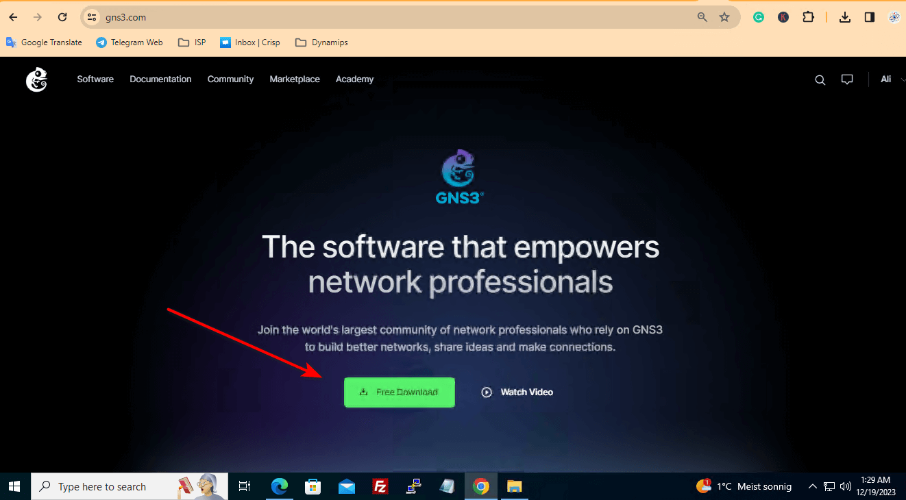
2-1. To download the GNS3 installer and the GNS3 VM file, go to the GNS3 website and click on the → Download button. You should see a page like the screenshot below.
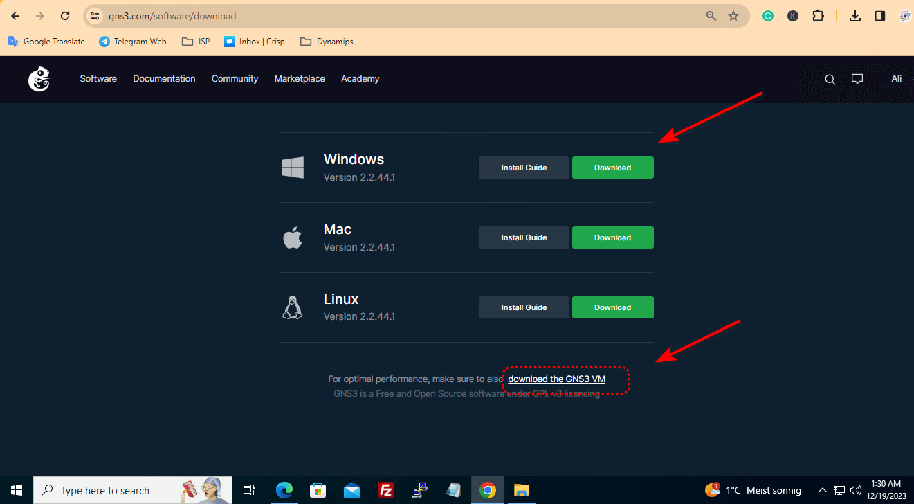
Choose the version of GNS3 that matches your operating system and click on the → Download button. You should see two files being downloaded: the GNS3 installer and the GNS3 VM file. The GNS3 installer is an executable file that will install the GNS3 software on your Windows PC. The GNS3 VM file is a zip file that contains the GNS3 virtual machine that will run on your VMware Player.
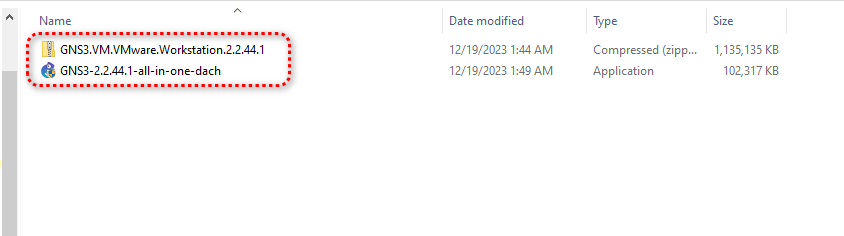
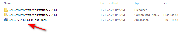
2-2. After the download is complete, you should see the downloaded files like the screenshot below.
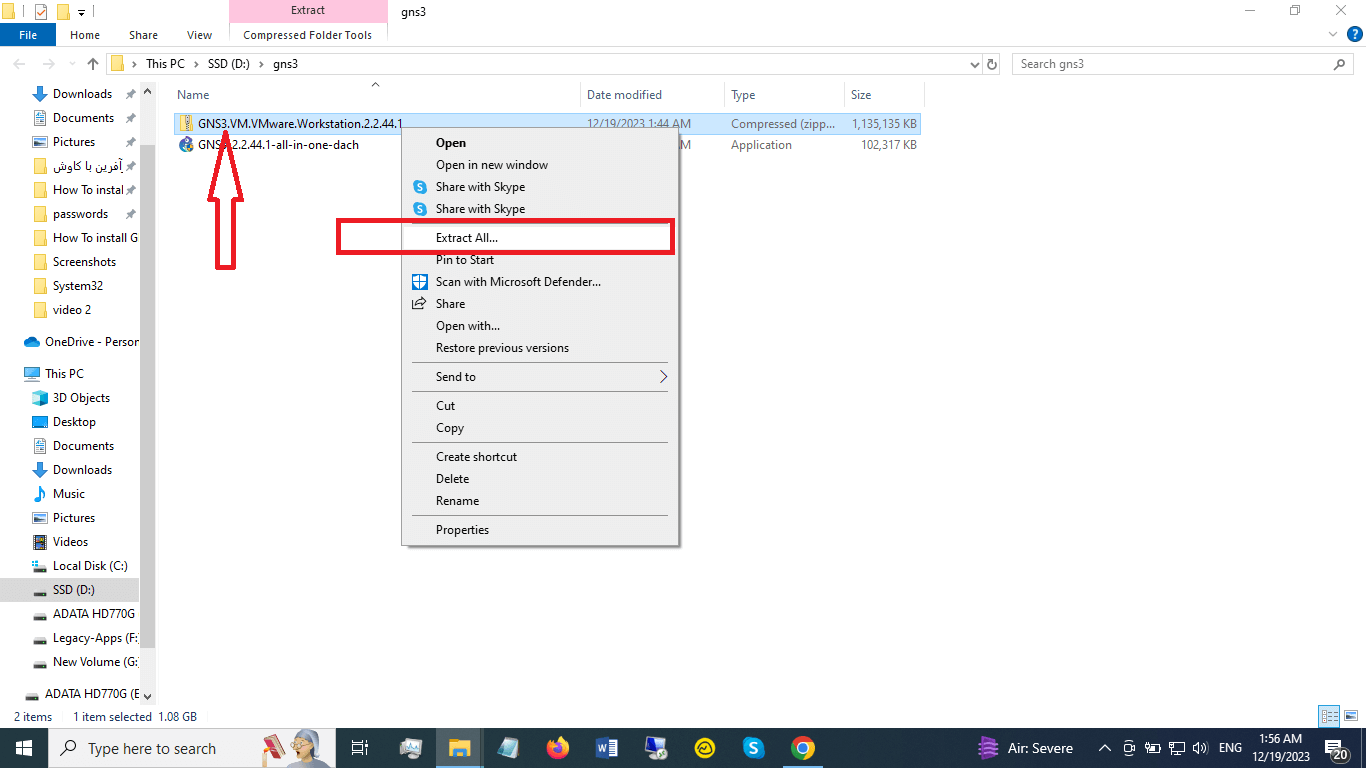
2.3- The GNS3 VM file is a zip file that you need to extract to get the ovf format that can be imported to your VMware Player. To extract the file, right-click on it and select → Extract All option.
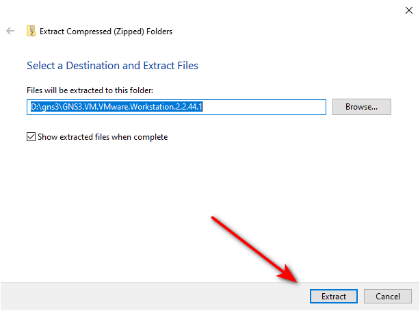
2-4. Then, choose a destination folder and click on the → Extract button.
2-5. After the extraction is done, you need to go to the destination folder to see the ovf file of the GNS3 VM.
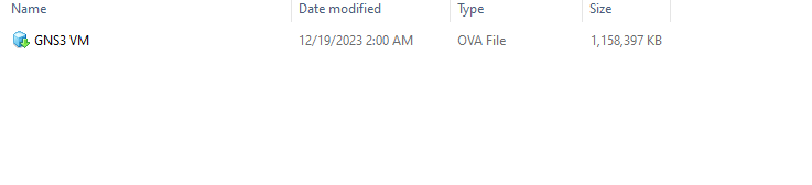
2-6- The ovf file is the file that you need to import to your VMware Player to create the GNS3 virtual machine.
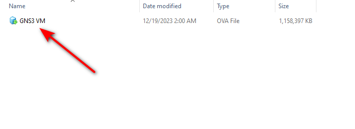
2-7. To import the file, double-click on the GNS3 VM file and then the VMware Player will open.
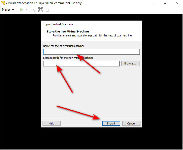
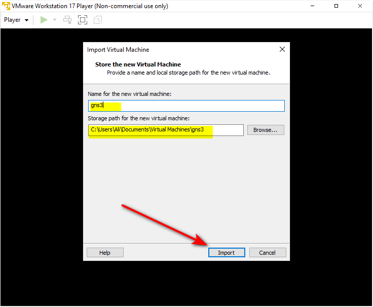
2-8. Then, you need to give the virtual machine a name, choose a location to store it, and click on the →Import button.
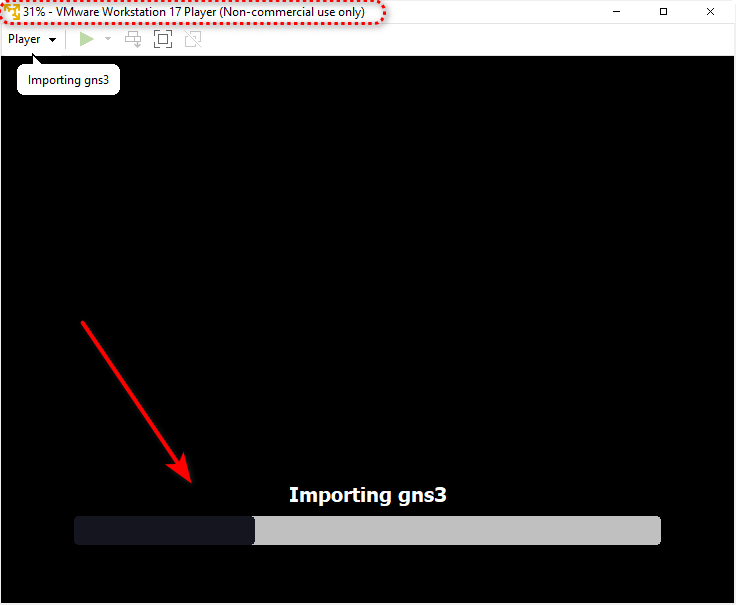
The import process may take some time, depending on the speed of your PC and the size of the file. You can see the progress of the import process on the VMware Player window.
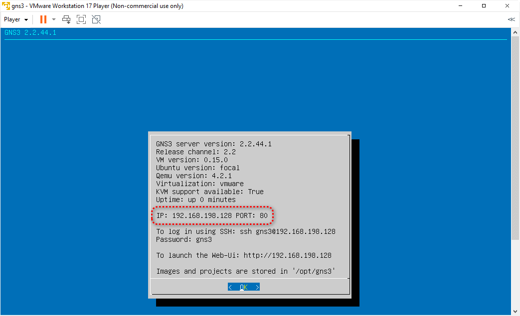
2-9. When the import is finished, the GNS3 VM will start automatically. You need to wait until the GNS3 VM is fully booted and shows you its IP address.
2-10. Now, you need to install the GNS3 software on your Windows PC. To do that, double-click on the GNS3 installer file that you downloaded earlier.
Finalizing Your GNS3 Configuration
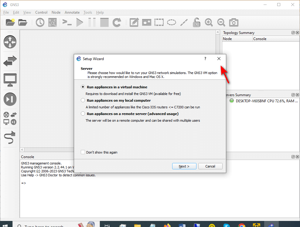
The GNS3 installer will launch and guide you through the installation process.The installer contains several components, such as Wireshark, Winpcap, SuperPutty, and the GNS3 software itself. You need to install all of them and accept the license agreements.
If you need more help with the installation process, you can watch the video instructions that I prepared for you. The video will show you how to install the GNS3 software and the GNS3 VM step by step.
Congratulations, you have successfully installed GNS3 on your VMware Player.
Now, you can → Close this window and start using GNS3 to create and test your network scenarios.
Step 3. How to Connect GNS3 VM to GNS3 Software
After installing the GNS3 software and the GNS3 VM, you need to connect them to use the advanced features of GNS3, such as running qemu images. Unlike EVE-NG, GNS3 is not a client-less emulator. It requires a connection between the virtual machine and the graphical user interface, which is the GNS3 software.
First Steps After Installing GNS3
To establish the connection, follow these steps:
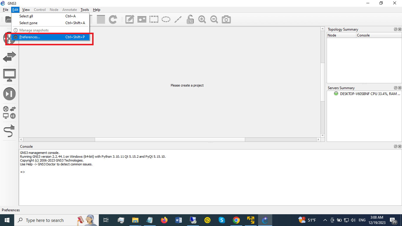
3-1. Open the GNS3 software and go to Edit → Preferences.
3-2. In the Preferences window, select GNS3 VM from the left pane.
3-3. In the GNS3 VM preferences, check the box that says “Enable the GNS3 VM”.
3-4. From the drop-down menu you need to select VMware Workstation/Player, then select the GNS3 VM.
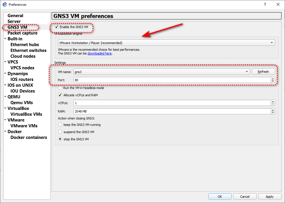
3-5. Adjust the number of vCPUs and the amount of memory for the GNS3 VM according to your needs.
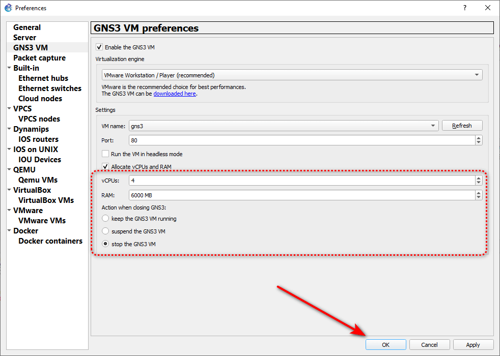
For example, if you want to install IOSv router in GNS3, you may need 4 vCPUs and 6 GB of memory.
3-6. Click OK to save the settings and close the Preferences window.
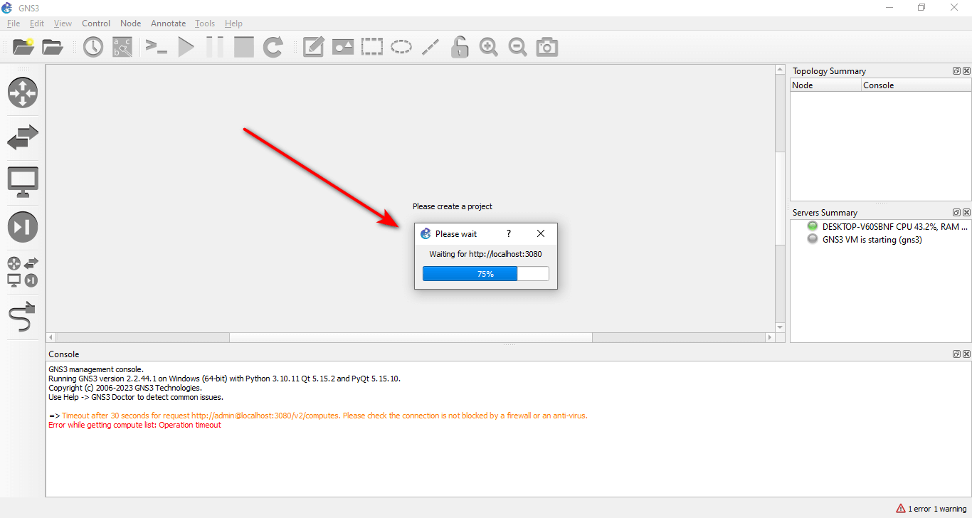
3-7. You should see a message that says “Connecting to the GNS3 VM” at the bottom of the GNS3 software window. Wait for a few seconds until the connection is established.
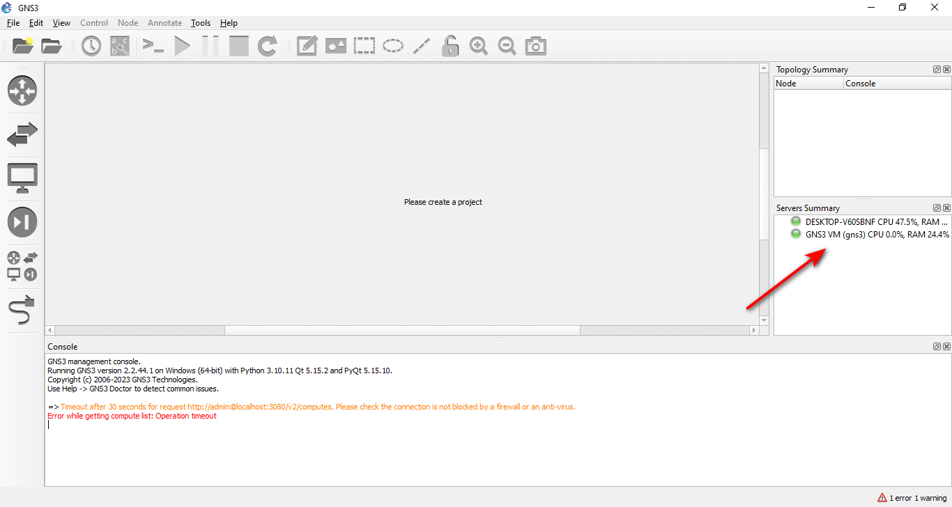
3-8. You should see the GNS3 VM status in green in the server summary section of the GNS3 software window. This means that the GNS3 software is connected to the GNS3 VM and you can use it for your network simulations.
Step 4. Starting with GNS3: Your First Project
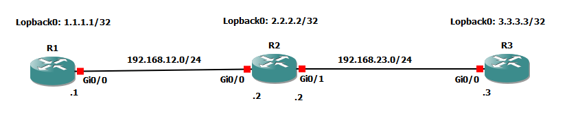
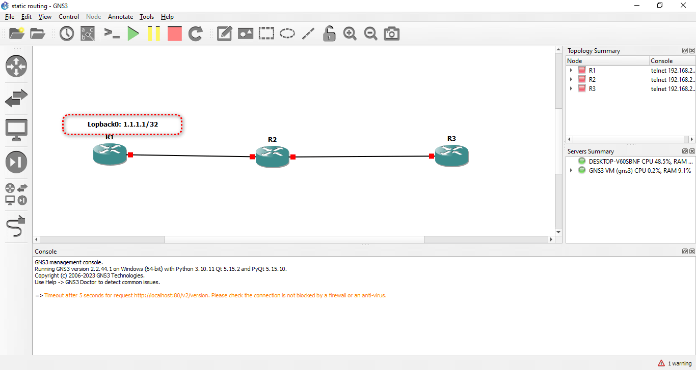
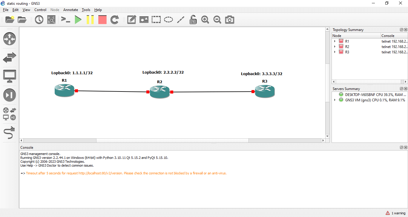
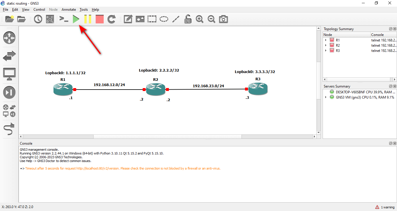
After installing the GNS3 software and the GNS3 VM, you can create your first lab in GNS3. In this GNS3 lab, we will create a simple static routing scenario with three IOSv routers like the screenshot below.
To create your first lab in GNS3, follow these steps:
4-1. Open the GNS3 software and go to File → New blank project.
4-2. Give your project a name, such as Static Routing, and click → OK.
4-3. You should see a blank workspace where you can add and connect devices. Before you do that, you need to add an IOSv router image to GNS3. This image is a virtual router that runs Cisco IOS software.
Enter your email address in the form below to receive the file.
Completing Your GNS3 Setup
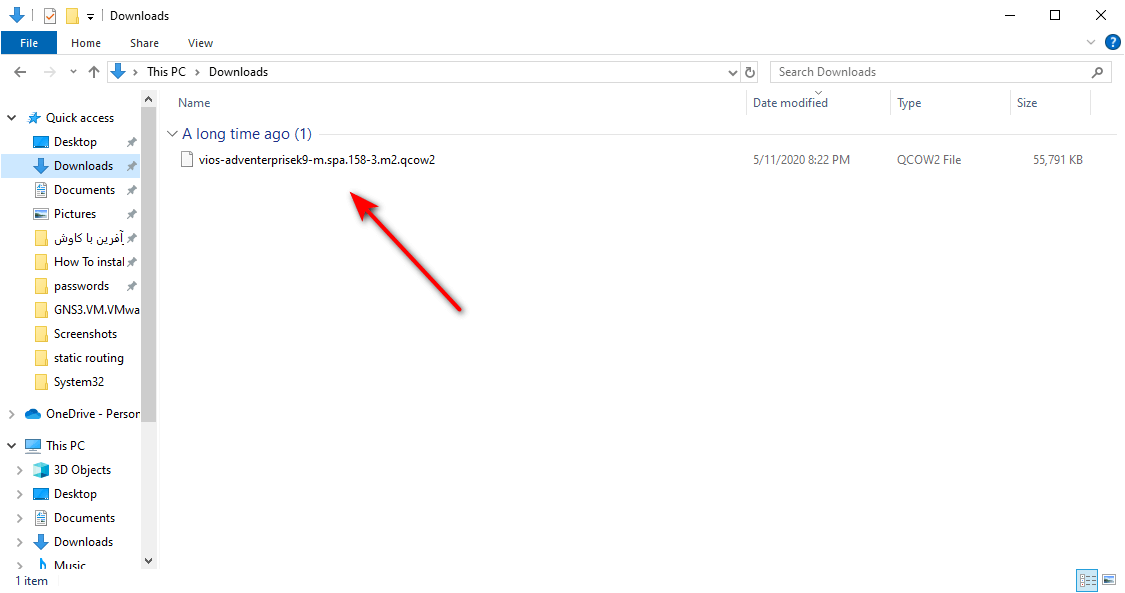
4-4. After you download the IOSv image, make sure it is located in your Downloads folder in Windows. You should see a file named → vios-adventerprisek9-m.spa.158-3.m2.qcow2
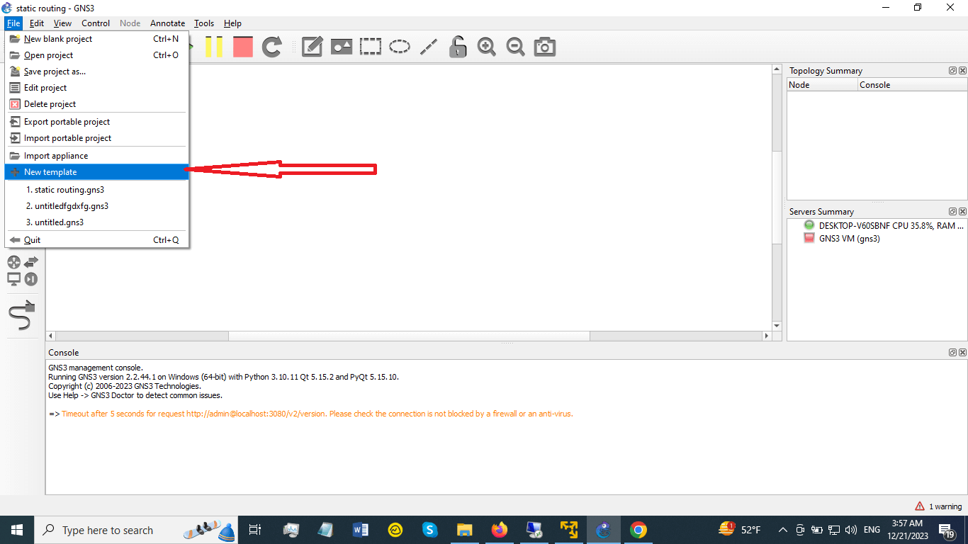
4-5. To add the IOSv image to GNS3, go to File → New template.
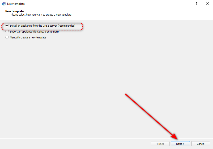
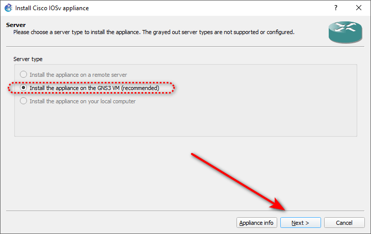
4-6. In the New template window, accept the default settings and click → Next.
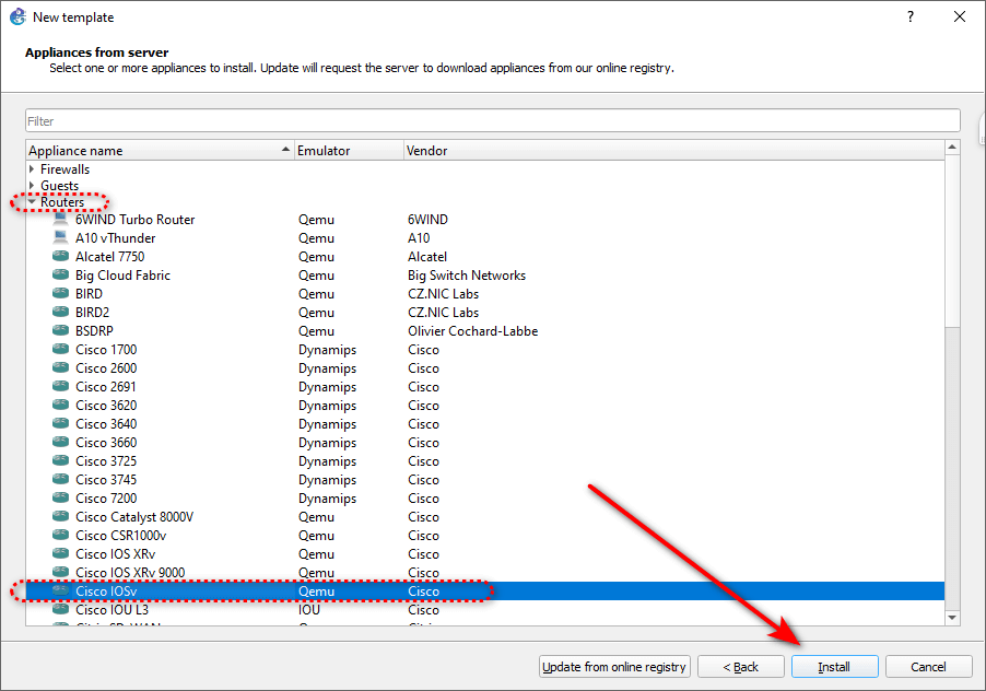
4-7. In the Device list, expand the Routers category and select IOSv. Then, click → Install.
4-8. In the IOSv settings, accept the default settings and click → Next.
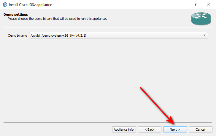
4-9. In the Binary image window, click → Next to accept the default binary.
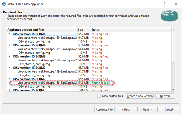
4-10. In the next window, you should see the IOSv image that you downloaded earlier. If you don’t see it, make sure the file is located in the Downloads folder in Windows. Then, click → Next.
4-11. In the next window, you need to download another file called IOSv_startup_config.img. This file is a startup configuration file for the IOSv router. To download it, select the file and click → Download.
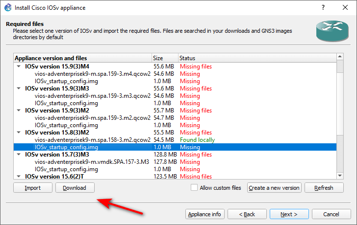
4-12. You will be redirected to a website where you can download the file.
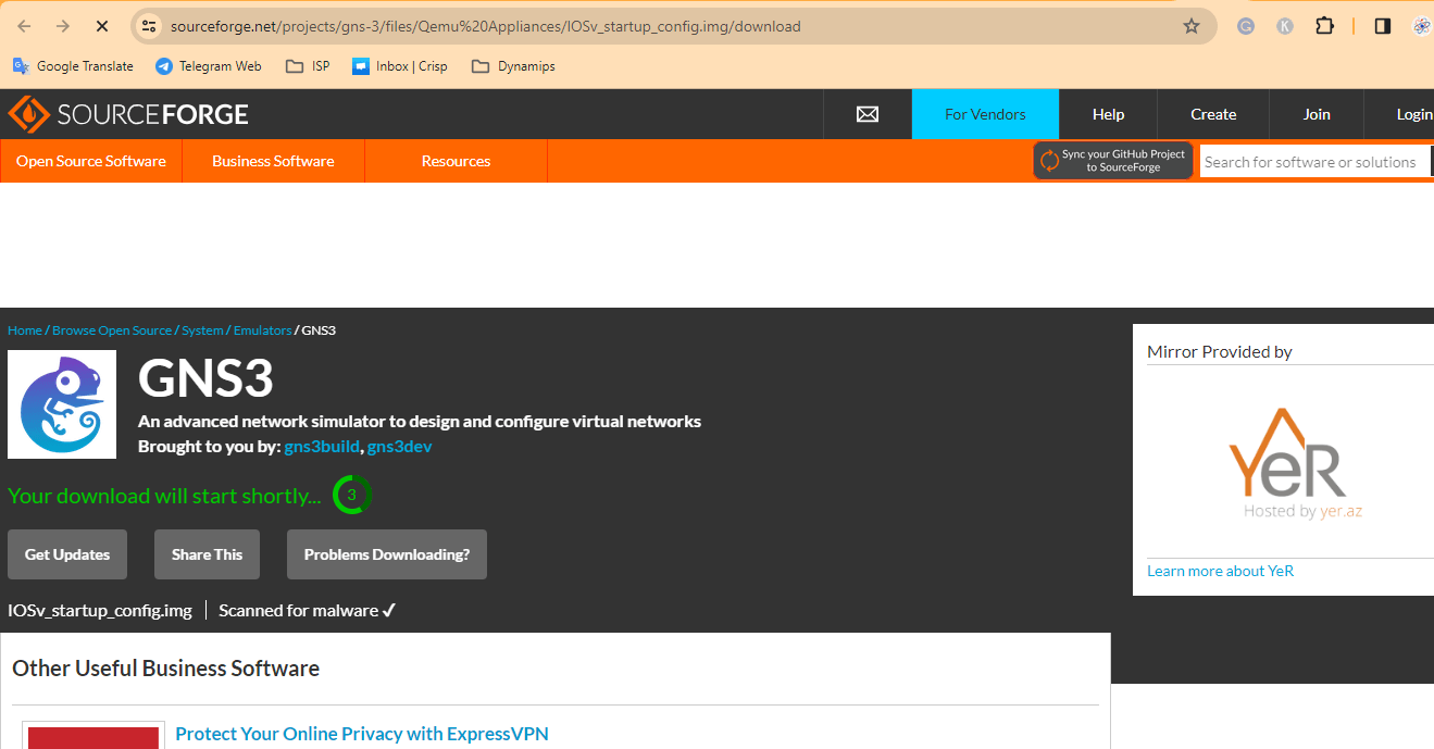
Wait for a few seconds and then save the file to your Downloads folder in Windows.
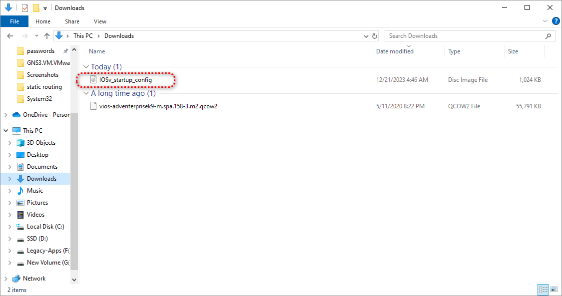
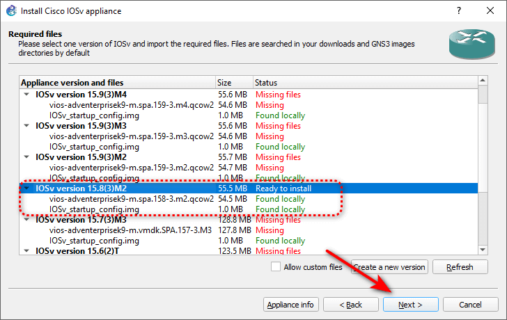
4-13. Go back to the New template window and click Refresh. You should see the IOSv_startup_config.img file ready. Then, click → Next.
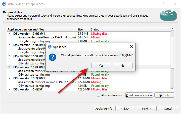
4-14. In the next window, click → Yes to accept the installation of the IOSv router.
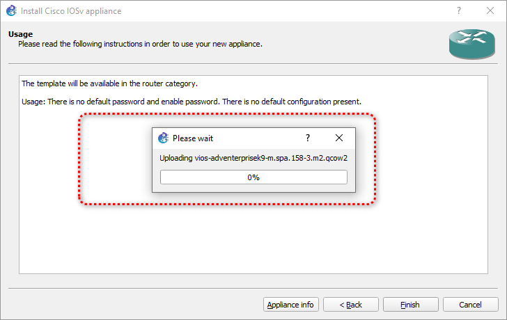
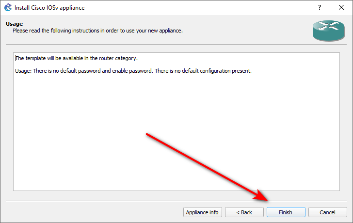
4-15. The wizard will start to upload the IOSv qemu image to the GNS3 VM. Wait for the process to finish and then click → Finish.
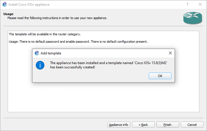
4-16. You should see a confirmation window that says “Cisco IOSv Template successfully created “. Click → OK to close it.
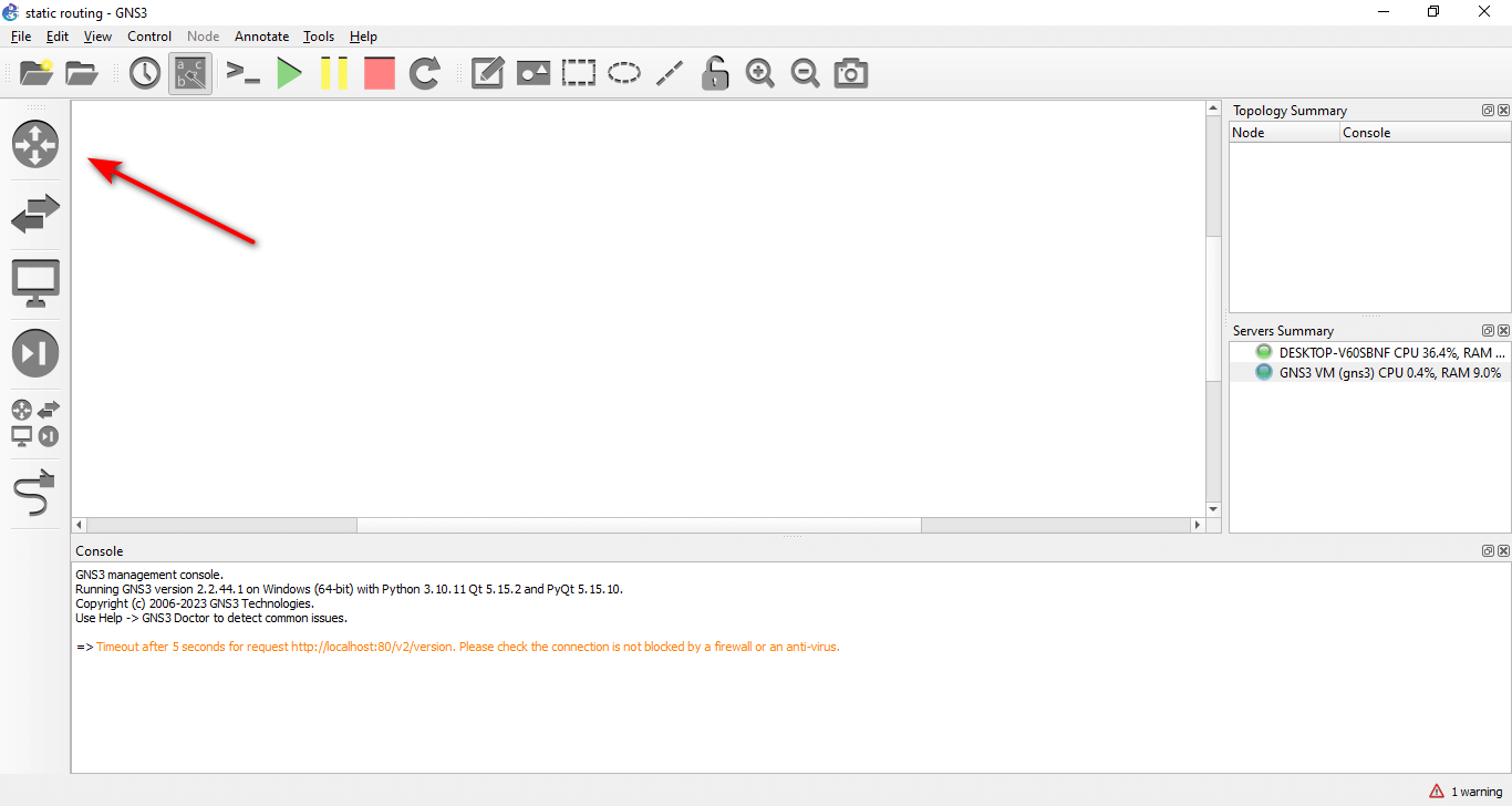
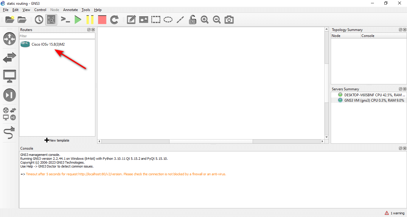
4-17. To see the IOSv router in GNS3, click on the → Routers icon in the left pane.
Acquiring the Right Files to Install GNS3
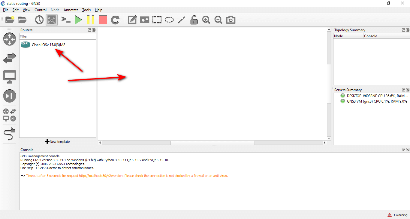
4-18. You should see the IOSv router in the list of available routers. You can drag and drop it to the workspace to add it to your lab.
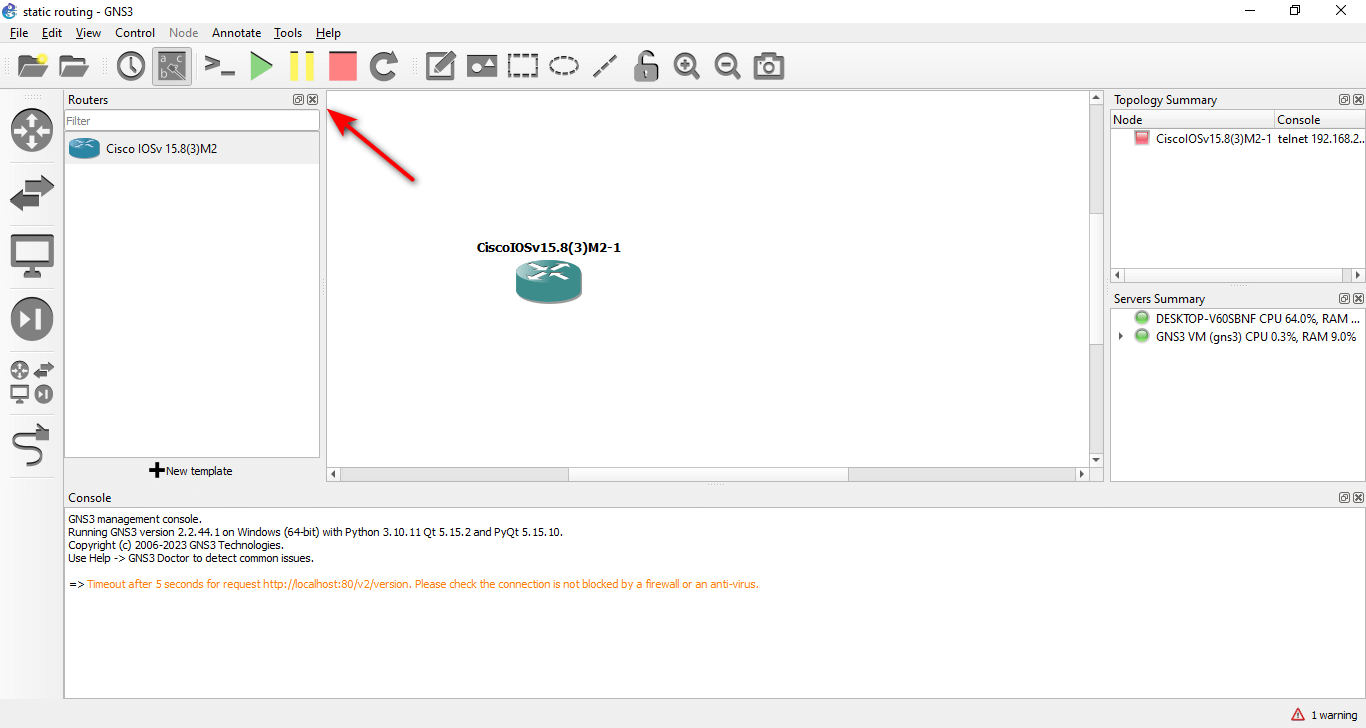
4-19. To close the Routers list, click on the → X icon in the top right corner.
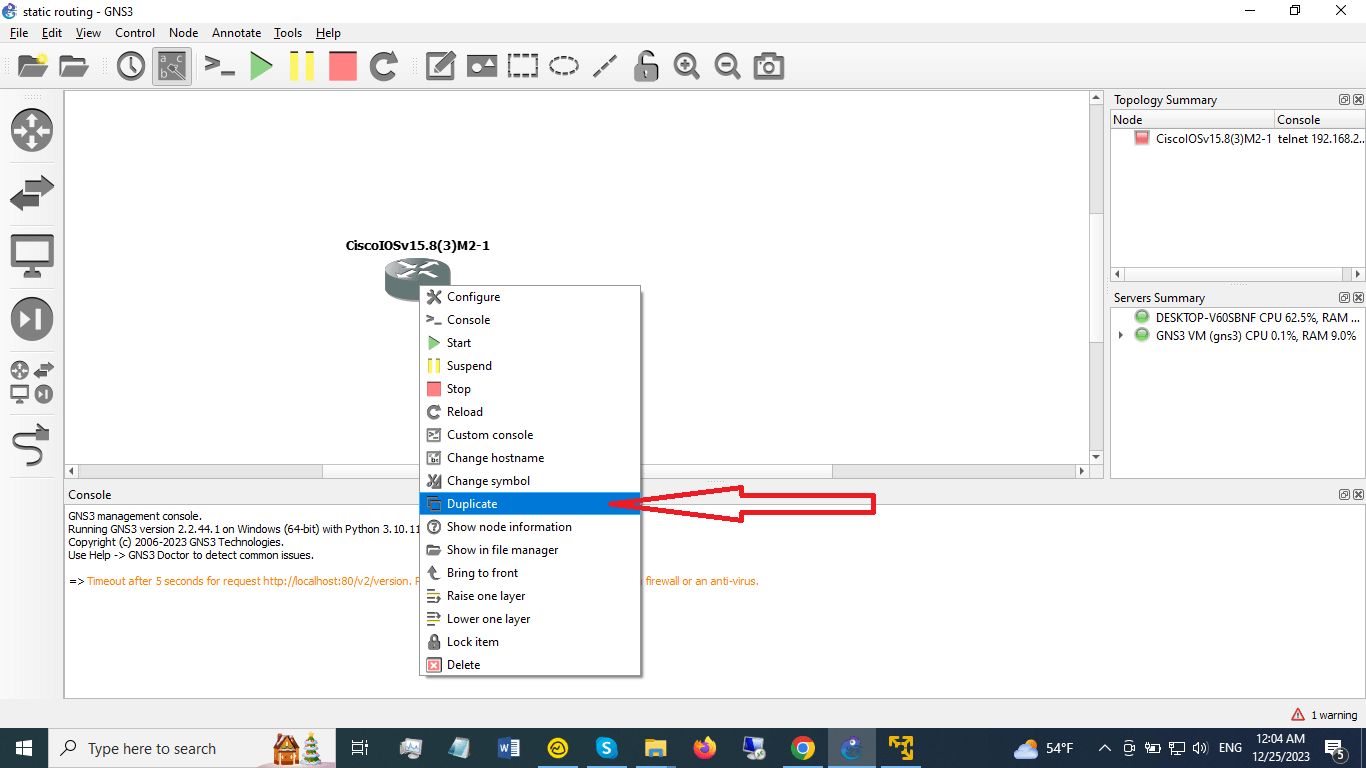
4-20. To add more IOSv routers to your lab, you can right-click on the existing router and select → Duplicate. You need three IOSv routers for this lab.
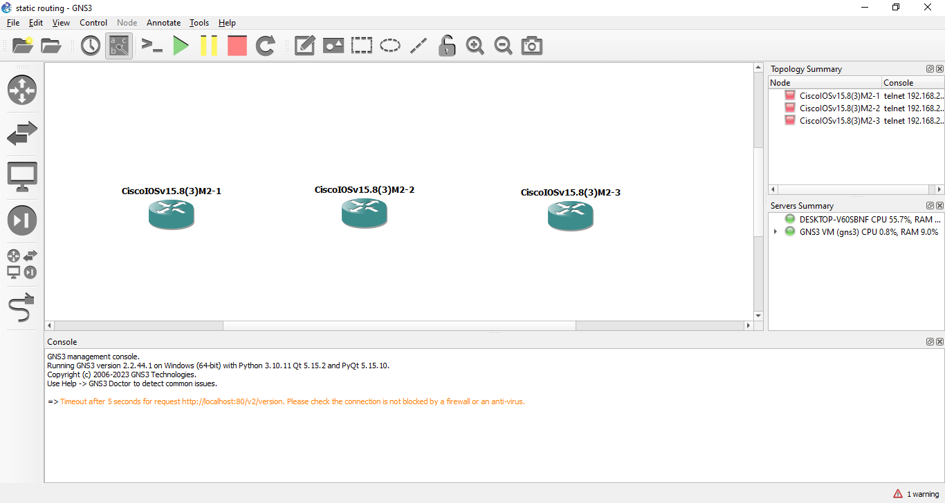
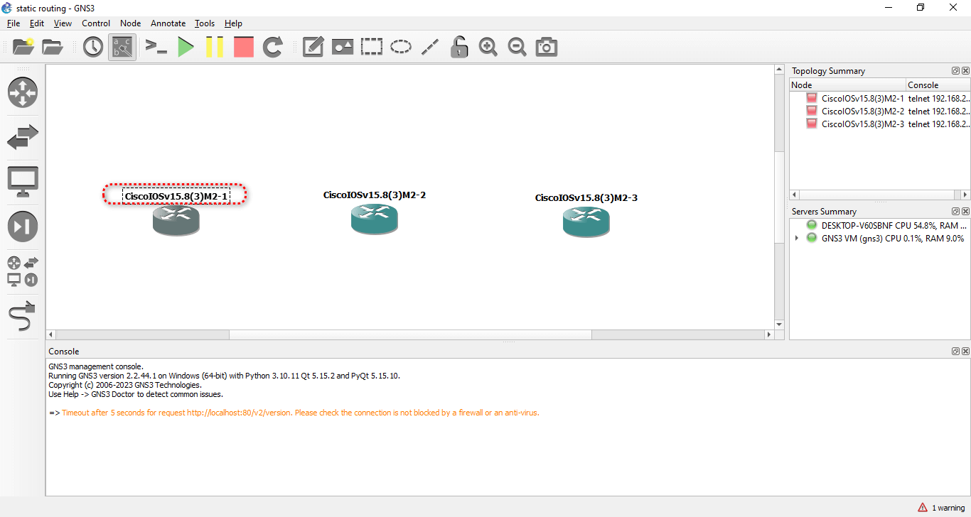
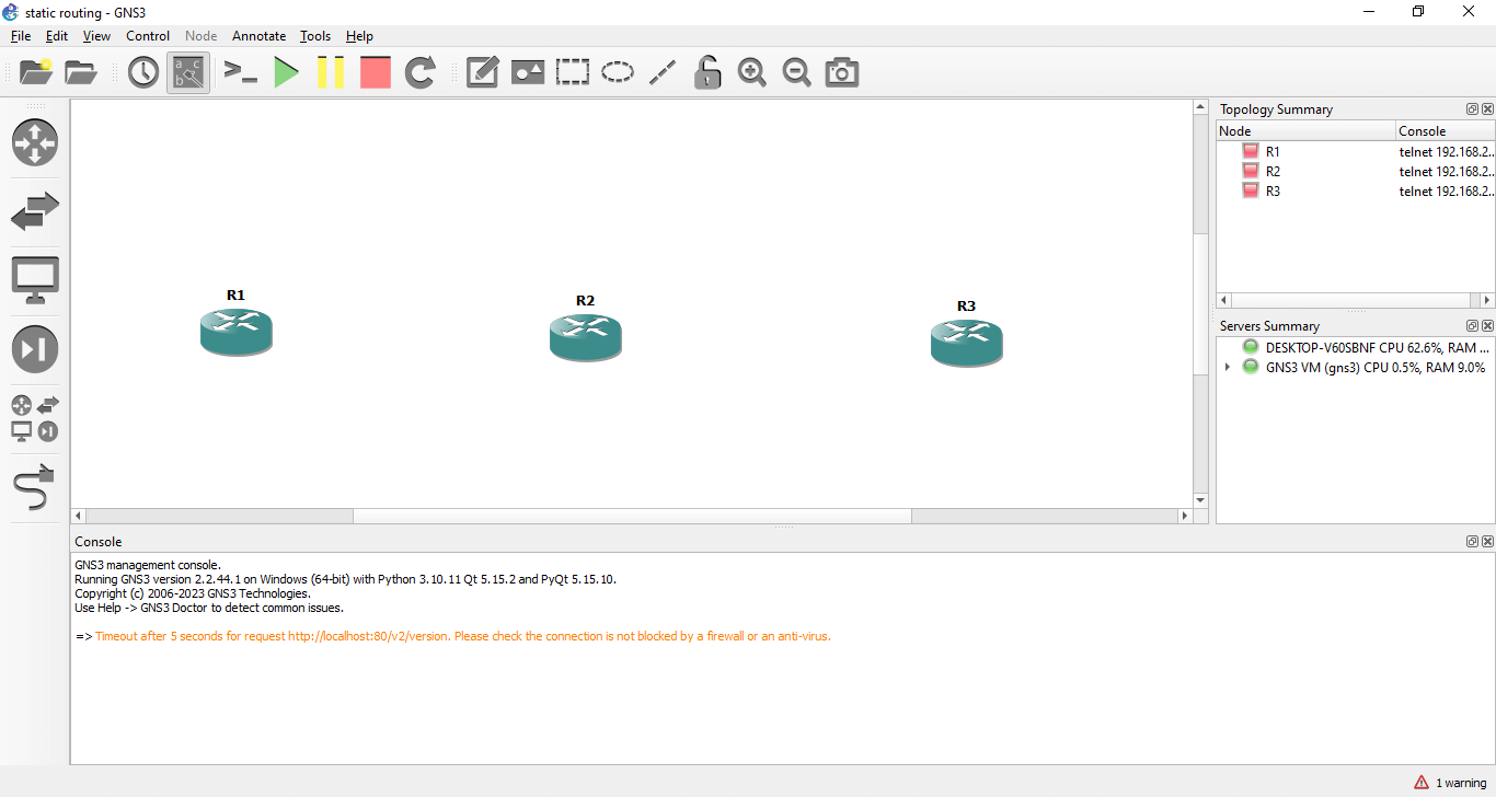
4-21. You should see three routers in your workspace. You can rename them by double-clicking on their names and typing new ones. For example, you can name them R1, R2, and R3.
4-22. To connect the routers to each other, click on the → Plug icon in the top toolbar. This will allow you to create links between devices.
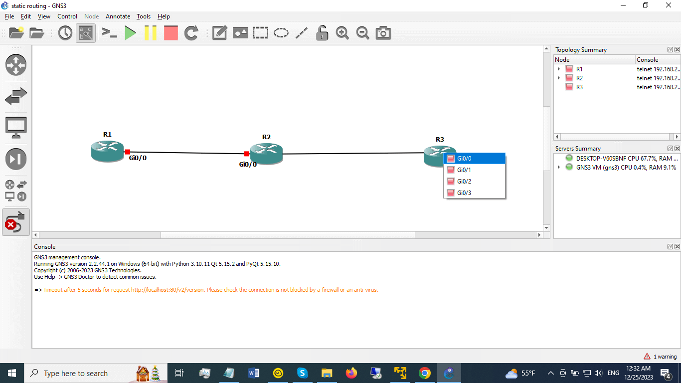
4-23. To create a link, click on a router and select an interface. For example, click on → R1 and select g0/0.
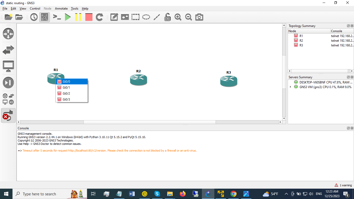
Then, move your mouse over another router and select an interface. For example, move your mouse over R2 and select g0/0. This will create a link between R1 and R2 using their g0/0 interfaces.
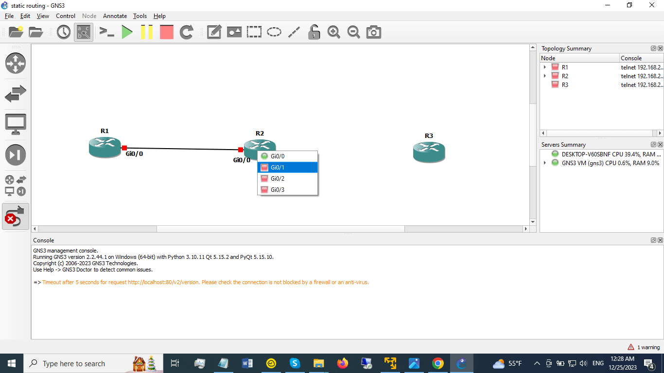
4-24. Repeat the same process to create a link between R2 and R3 using their g0/1 and g0/0 interfaces, respectively.
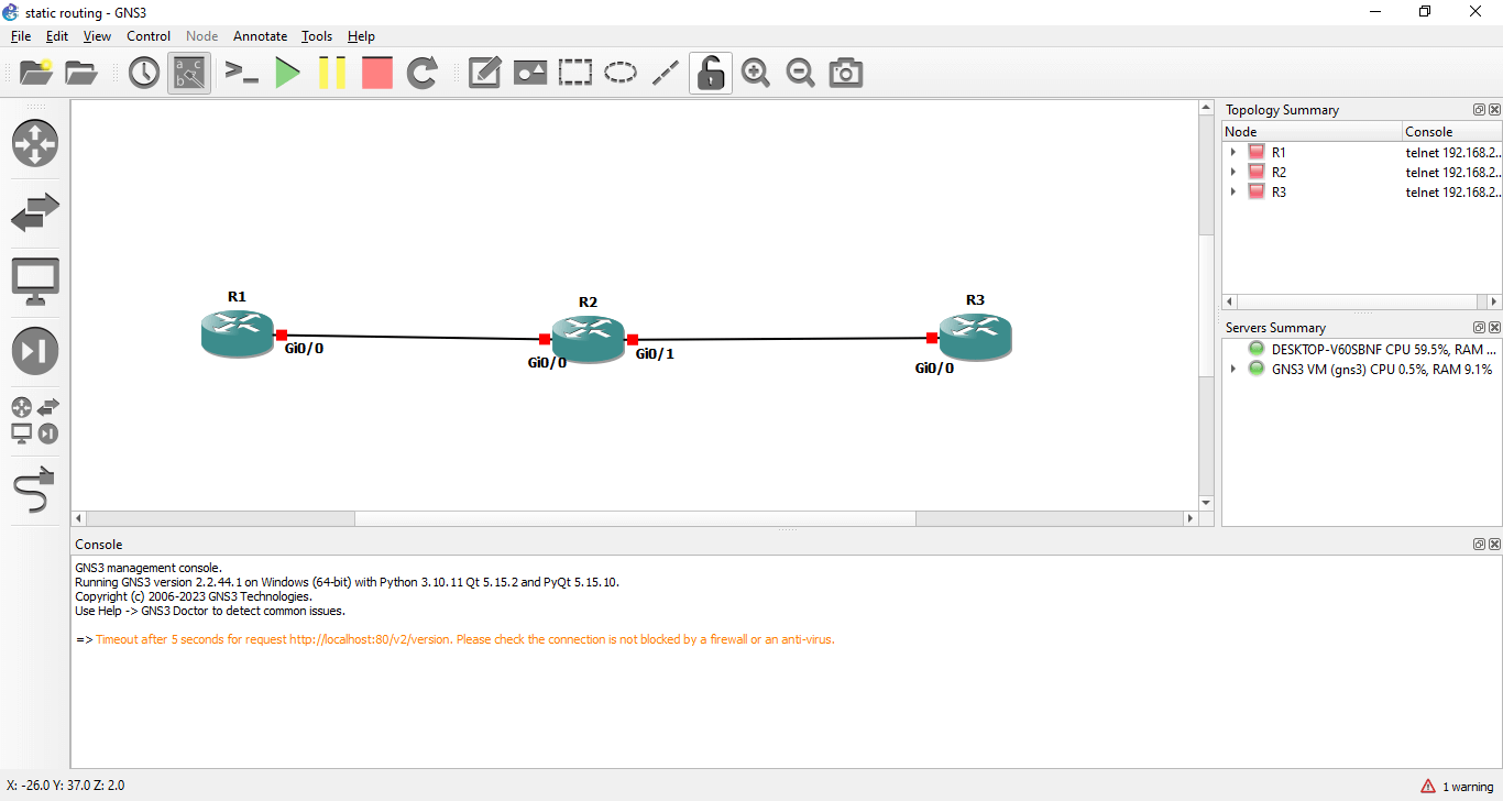
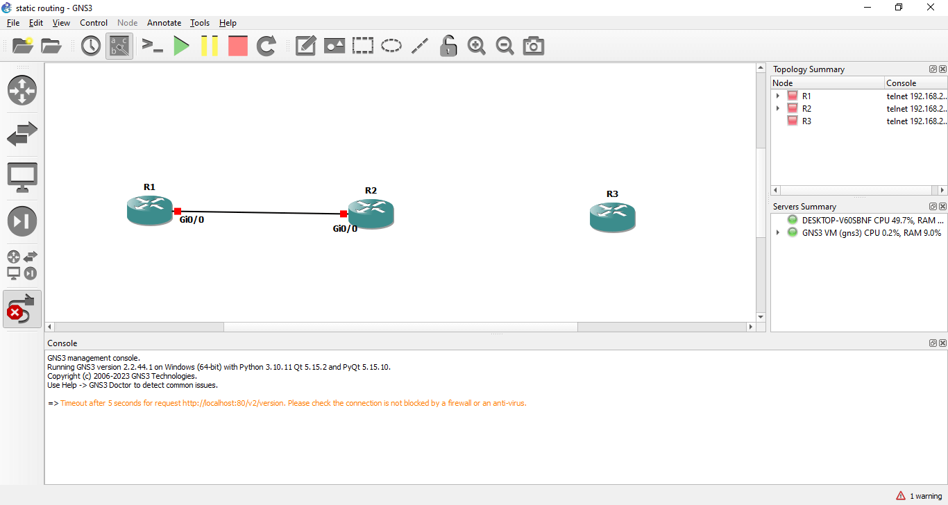
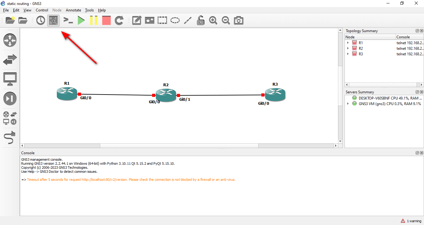
4-25. You should see two links connecting the three routers. If you can’t see the interface labels, you can click on the → Show/Hide interface labels icon in the top toolbar.
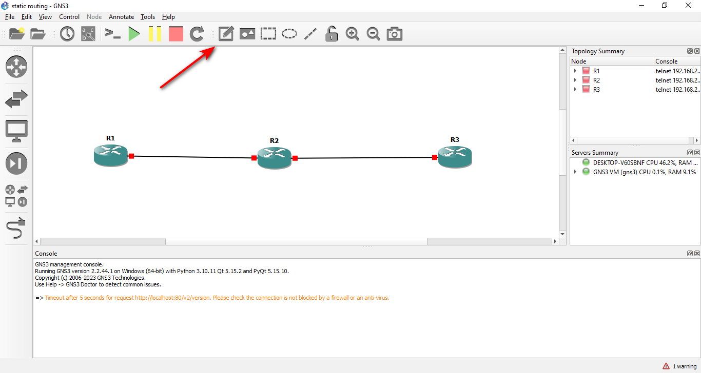
4-26. To add some text to your lab, you can click on the Text icon in the top toolbar. This will allow you to add text boxes to your workspace. You can use them to label your devices and links with IP addresses and other information.
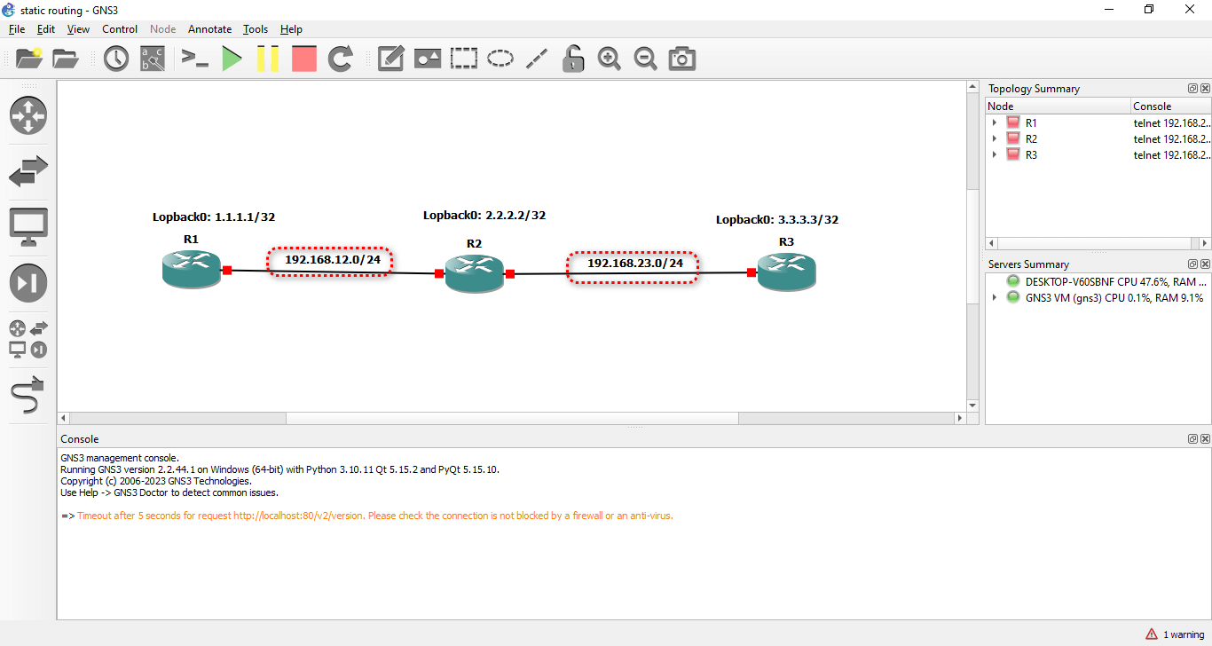
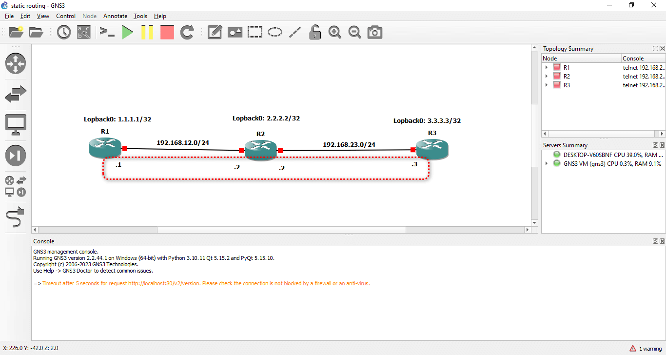
4-27. For example, you can add a text box above R1 and type 10.0.0.1/24. This is the IP address of R1’s g0/0 interface. You can also add a text box below the link between R1 and R2 and type 10.0.0.0/24. This is the network address of the link between R1 and R2.
4-28. Repeat the same process to add text boxes for the other devices and links. You can use the following IP addresses for this lab:
- R1 g0/0: 10.0.0.1/24
- R2 g0/0: 10.0.0.2/24
- R2 g0/1: 10.0.1.1/24
- R3 g0/0: 10.0.1.2/24
You should see a lab similar to the screenshots below.
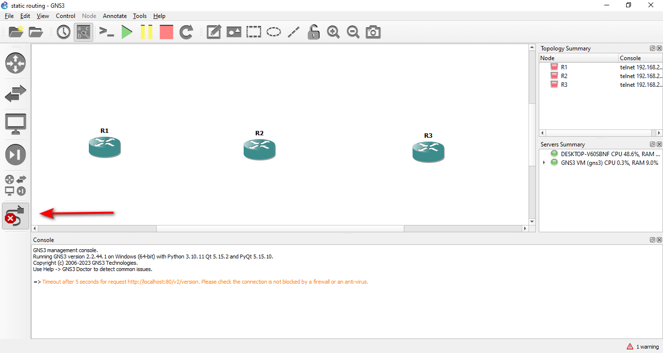
4-29. You have successfully created your first lab in GNS3. To save it, go to File → Save project. Right-click on each device device and select Start or click on start icon in the gns3 main menu to start all nodes.
Step 5. Configure Static Routing on the Cisco Routers
Lab Objective: The objective of this lab is to configure static routes via Ethernet interfaces between three routers. You will also verify the configured static routes using ping and traceroute commands.
Lab Purpose: Static route configuration is a fundamental skill for network engineers. There are several methods to configure static routes on a Cisco router, and each method has its advantages and disadvantages. As a Cisco engineer and in the Cisco CCNA exam, you will be expected to know how to configure static routes using any of the methods available in Cisco IOS.
LAB: Static Route v1.0
Level: CCNA / Basic
Approximate time: 20 minutes
Preferred image: vios-adventerprisek9-m.spa.158-3.m2.qcow2
This LAB will cover topics from Chapter 16: Configuring IPv4 Addresses and Static Routes.
For more information, we suggest “CCNA 200-301, Volume 1 Official Cert Guide.”
Commands Guide:
All commands in this document have this style:
 # Interface gig 0/0
If any option specified with italic letters means that you must replace the keyword with a desired value, for example:
 # ip address ip_address  subnet_mask
 # ip address 192.168.10.1 255.255.255.0
And finally, if we mention something in {}, it means that you must use one of the options
 # Show ip route
Table 1 – LAB Addressing (here is the table where you can see all the IP addresses for router interfaces in this lab)
| Router | LoopBack 0 | Gi 0/0 | Gi 0/1 |
| R1 | 1.1.1.1/32 | 192.168.12.1/24 | — |
| R2 | 2.2.2.2/32 | 192.168.12.2/24 | 192.168.23.2/24 |
| R3 | 3.3.3.3/32 | 192.168.23.3/24 | — |
First, you need to start all the routers by clicking on the start icon.
Now, you can start the lab configuration. We have provided tasks, an IP table, and step-by-step instructions (workbook) to help you understand how to start from scratch and finish your lab successfully.
Task 1
Configure the hostnames on routers R1, R2, R3 as shown in the topology. Assign the IP addresses as mentioned in Table 1.
| Router | LoopBack 0 | Gi 0/0 | Gi 0/1 |
| R1 | 1.1.1.1/32 | 192.168.12.1/24 | — |
| R2 | 2.2.2.2/32 | 192.168.12.2/24 | 192.168.23.2/24 |
| R3 | 3.3.3.3/32 | 192.168.23.3/24 | — |
Go to R1 and double-click on the router to open the console. Enter the following commands to configure the hostname and the IP addresses.
Router>en
Router#conf ter
Enter configuration commands, one per line.  End with CNTL/Z.
Router(config)#hostname R1
R1(config)#interface gi 0/0
R1(config-if)#ip add 192.168.12.1 255.255.255.0
R1(config-if)#no shut
R1(config-if)#exit
R1(config)#interface loopback 0
R1(config-if)#1.1.1.1
R1(config-if)#ip address 1.1.1.1 255.255.255.255
R1(config-if)#end
R1#show ip interface brief
Interface                  IP-Address      OK? Method Status                Protocol
GigabitEthernet0/0         192.168.12.1    YES manual up               up
GigabitEthernet0/1         unassigned      YES unset  administratively down down
GigabitEthernet0/2         unassigned      YES unset  administratively down down
GigabitEthernet0/3         unassigned      YES unset  administratively down down
Loopback0                  1.1.1.1         YES manual up               up
R1#
Go to R2 and enter the following commands to configure the hostname and the IP addresses.
Router>en
Router#conf ter
Enter configuration commands, one per line.  End with CNTL/Z.
Router(config)#hostname R2
R2(config)#interface gi 0/0
R2(config-if)#ip address 192.168.12.2 255.255.255.0
R2(config-if)#no shut
R2(config-if)#exit
R2(config)#interface loopback 0
R2(config-if)#ip address 2.2.2.2 255.255.255.255
R2(config-if)#no shut
R2(config-if)#exit
R2(config)#interface gi 0/1
R2(config-if)#ip address 192.168.23.2 255.255.255.0
R2(config-if)#no shut
R2(config)#end
R2#show ip interface brief
Interface                  IP-Address      OK? Method Status                Protocol
GigabitEthernet0/0         192.168.12.2    YES manual up                    up
GigabitEthernet0/1         192.168.23.2    YES manual up                    up
GigabitEthernet0/2         unassigned      YES unset  administratively down down
GigabitEthernet0/3         unassigned      YES unset  administratively down down
Loopback0
Go to R3 and enter the following commands to configure the hostname and the IP addresses.
Router>en
Router#conf ter
Enter configuration commands, one per line.  End with CNTL/Z.
Router(config)#hostname R3
R3(config)#interface gi 0/0
R3(config-if)#ip address 192.168.23.3 255.255.255.0
R3(config-if)#no shut
R3(config-if)#
*Sep 26 13:57:39.161: %LINK-3-UPDOWN: Interface GigabitEthernet0/0, changed state to up
*Sep 26 13:57:40.162: %LINEPROTO-5-UPDOWN: Line protocol on Interface GigabitEthernet0/0, changed state to up
R3(config-if)#exit
R3(config)#interfce loop
R3(config)#interf
R3(config)#interface loo
R3(config)#interface loopback 0
R3(config-if)#ip addr
*Sep 26 13:57:59.991: %LINEPROTO-5-UPDOWN: Line protocol on Interface Loopback0, changed state to upes
R3(config-if)#ip address 3.3.3.3 255.255.255.255
R3(config-if)#no shut
R3(config-if)#exit
R3(config)#exit
R3#
*Sep 26 13:58:15.458: %SYS-5-CONFIG_I: Configured from console by console
R3#show ip interfac
R3#show ip interface brief
Interface                  IP-Address      OK? Method Status                Protocol
GigabitEthernet0/0         192.168.23.3    YES manual up                    up
GigabitEthernet0/1         unassigned      YES unset  administratively down down
GigabitEthernet0/2         unassigned      YES unset  administratively down down
GigabitEthernet0/3         unassigned      YES unset  administratively down down
Loopback0                  3.3.3.3         YES manual up                    up
R3#
Task 2
Configure static routes on the routers.
R1 Configuration:
According to the diagram, R1 needs to reach 2.2.2.2/32, 3.3.3.3/32, and 192.168.23.0/24 networks. All of these networks are reachable via R2. So, we have to configure three static routes on R1 to make this possible. Alternatively, we could configure a default route to R2, but for now, we will use three separate routes. See the example below:
R1>en
R1#conf ter
Enter configuration commands, one per line.  End with CNTL/Z.
R1(config)#ip route 192.168.23.0 255.255.255.0 192.168.12.2
R1(config)#ip route 2.2.2.2 255.255.255.255 192.168.12.2
R1(config)#ip route 3.3.3.3 255.255.255.255 192.168.12.2
R1(config)#
With these commands, R1 can reach R3, for example, but R3 does not know where 1.1.1.1/32 is and how to reach it. So, we need to configure R2 and R3 as well.
Go to R2 and check the routing table. As you can see, R2 has two connected routes for 192.168.12.0/24 and 192.168.23.0/24. So, we need to configure two static routes for 1.1.1.1/32 and 3.3.3.3/32.
R2>en
R2 #show ip route
Codes: L - local, C - connected, S - static, R - RIP, M - mobile, B - BGP
       D - EIGRP, EX - EIGRP external, O - OSPF, IA - OSPF inter area
       N1 - OSPF NSSA external type 1, N2 - OSPF NSSA external type 2
       E1 - OSPF external type 1, E2 - OSPF external type 2
       i - IS-IS, su - IS-IS summary, L1 - IS-IS level-1, L2 - IS-IS level-2
       ia - IS-IS inter area, * - candidate default, U - per-user static route
       o - ODR, P - periodic downloaded static route, H - NHRP, l - LISP
       a - application route
       + - replicated route, % - next hop override, p - overrides from PfR


Gateway of last resort is not set


      2.0.0.0/32 is subnetted, 1 subnets
C        2.2.2.2 is directly connected, Loopback0
      192.168.12.0/24 is variably subnetted, 2 subnets, 2 masks
C        192.168.12.0/24 is directly connected, GigabitEthernet0/0
L        192.168.12.2/32 is directly connected, GigabitEthernet0/0
      192.168.23.0/24 is variably subnetted, 2 subnets, 2 masks
C        192.168.23.0/24 is directly connected, GigabitEthernet0/1
L        192.168.23.2/32 is directly connected, GigabitEthernet0/1
R2#conf ter
Enter configuration commands, one per line.  End with CNTL/Z.
R2(config)#ip route 1.1.1.1 255.255.255.255 192.168.12.1
R2(config)#ip route 3.3.3.3 255.255.255.255 192.168.23.3
R2(config)#
R3 configuration almost is the same with R1. We need 3 routes for 1.1.1.1/32, 2.2.2.2/32 and 192.168.12.0/24. But this time, let’s use a default gateway instead!
R3>en
R3#conf ter
Enter configuration commands, one per line.  End with CNTL/Z.
R3(config)#ip route 0.0.0.0 0.0.0.0 192.168.23.2
R3(config)#exit
Task 3
After completing our configuration, let’s check it with ping and traceroute commands.
We did the test just from R3, but you can do the same thing from the others.
R3#ping 1.1.1.1 source 3.3.3.3
Type escape sequence to abort.
Sending 5, 100-byte ICMP Echos to 1.1.1.1, timeout is 2 seconds:
Packet sent with a source address of 3.3.3.3
!!!!!
Success rate is 100 percent (5/5), round-trip min/avg/max = 4/5/7 ms
R3#traceroute 1.1.1.1 source 3.3.3.3
Type escape sequence to abort.
Tracing the route to 1.1.1.1
VRF info: (vrf in name/id, vrf out name/id)
  1 192.168.23.2 3 msec 3 msec 3 msec
  2 192.168.12.1 8 msec 12 msec *
R3#
Next Steps
You have successfully installed GNS3 on your Windows 10 computer and learned how to use it to create and run network projects. You are now ready to take your networking skills to the next level with GNS3 Full Pack images.
GNS3 Full Pack images is a package that includes Cisco images for use in GNS3. It can help you learn and practice CCNA and CCIE, the most popular and prestigious Cisco certifications. With GNS3 Full Pack images, you can:
- Access a variety of Cisco devices, such as routers, switches, firewalls, and servers
- Configure, troubleshoot, and test complex network scenarios
- Prepare for the CCNA and CCIE exams with realistic lab environments
- Save time and money by avoiding the need to buy physical hardware
GNS3 Full Pack images are compatible with GNS3 and VMware Workstation. They are easy to install and use. They also come with a lifetime update.
To download GNS3 Full Pack images and start your journey to becoming a Cisco certified professional, click the button below.
