

This lab involves configuring and troubleshooting IPv6 static routing in a simulated environment. The network consists of two routers (R1 and R2) connected via an Ethernet link, with each router having a directly connected LAN. The key challenges in this scenario include:
- Assigning proper IPv6 addresses to router interfaces.
- Configuring static routes to ensure end-to-end connectivity.
- Verifying and troubleshooting routing table issues.
Your goal is to successfully configure and verify IPv6 static routing between routers.
Objective
By completing this lab, you will:
- Configure IPv6 addresses on multiple routers.
- Establish IPv6 static routes to enable inter-network communication.
- Verify IPv6 routing table entries and connectivity.
- Troubleshoot common static routing issues.
Network Structure
- Devices:
- Router (R1)
- Router (R2)
- PC (PC1)
- PC (PC2)
- Subnets and IP Addressing:
- R1 E0/0: 2001:DB8:1::1/64
- R1 E0/1:
2001:DB8:2::1/64 - R2 E0/0: 2001:DB8:3::1/64
- R2 E0/1: 2001:DB8:2::2/64
- PC1:
2001:DB8:1::2/64 PC2: 2001:DB8:3::2/64
- Protocols:
- IPv6 Static Routing
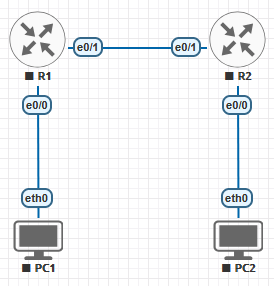
Topology Diagram
Prerequisites
- EVE-NG installed and operational.
- Two IOL-L3 routers (R1, R2) and two vPCS nodes (PC1, PC2).
- Understanding of IPv6 addressing and subnetting.
- Familiarity with Cisco CLI and routing commands.
- Knowledge of verification and troubleshooting techniques.
Implementation Steps
Step 1: Set Up the Topology
- Add two IOL-L3 routers (R1, R2) and two vPCS nodes (PC1, PC2) to the EVE-NG topology.
- Connect R1 and R2 via an Ethernet link.
- Connect PC1 to R1 and PC2 to R2 on separate Ethernet segments.
Step 2: Configure IPv6 Addresses on R1
Assign IPv6 addresses to the interfaces of R1 to enable communication with the LAN and the link to R2.
Router>enable
Router#configure terminal
Router(config)#hostname R1

R1(config)#interface ethernet0/0
R1(config-if)#ipv6 address 2001:DB8:1::1/64
R1(config-if)#no shutdown
R1(config-if)#exit

R1(config)#interface ethernet0/1
R1(config-if)#ipv6 address 2001:DB8:2::1/64
R1(config-if)#no shutdown
R1(config-if)#exit
R1(config)#
Why this step? Assigning IPv6 addresses on R1 ensures that it can communicate with both its LAN and R2.
Step 3: Configure IPv6 Addresses on R2
Assign IPv6 addresses to the interfaces of R2 to establish connectivity with the LAN and R1.
Router>enable
Router#configure terminal
Router(config)#hostname R2

R2(config)#interface ethernet0/0
R2(config-if)#ipv6 address 2001:DB8:3::1/64
R2(config-if)#no shutdown
*May 19 14:21:30.225: %LINK-3-UPDOWN: Interface Ethernet0/0, changed state to up
R2(config-if)#exit
R2(config)#interface ethernet0/1
R2(config-if)#ipv6 address 2001:DB8:2::2/64
R2(config-if)#no shutdown
*May 19 14:21:52.796: %LINK-3-UPDOWN: Interface Ethernet0/1, changed state to up
*May 19 14:21:53.796: %LINEPROTO-5-UPDOWN: Line protocol on Interface Ethernet0/1, changed state to up
R2(config-if)#exit
R2(config)#
Why this step? Assigning IPv6 addresses on R2 enables communication with both R1 and its local LAN.
Step 4: Verify IPv6 on R1 and R2
R1#show ipv6 interface brief
Ethernet0/0            [up/up]
    FE80::A8BB:CCFF:FE00:1000
    2001:DB8:1::1
Ethernet0/1            [up/up]
    FE80::A8BB:CCFF:FE00:1010
    2001:DB8:2::1
Ethernet0/2            [administratively down/down]
    unassigned
Ethernet0/3            [administratively down/down]
    unassigned